
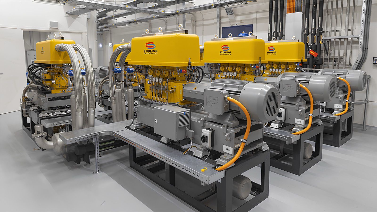

Liquid Hydrogen (LH₂) Systems — 2-Stage Stirling Cryogenerators by Stirling Cryogenics
Stirling Cryogenics’ hydrogen systems use a 2-stage Stirling cryogenerator that reaches 20 K to liquefy hydrogen gas and to re-liquefy the gas that boils off LH₂ storage tanks. A 1-cylinder machine produces 5 kg/day and a 4-cylinder machine 30 kg/day; several 4-cylinder machines in parallel in a 40 ft container reach up to 200 kg/day. Two Theta Technology works with Stirling Cryogenics on hydrogen projects in Thailand, quoted per project.
System layout
LH₂ production system sizes
A 2-stage Stirling cryogenerator reaches 20 K. Capacity scales by running several units in parallel; each runs independently, so if one stops the others keep producing.
| Configuration | LH₂ production |
|---|---|
| 1-cylinder machine | 5 kg/day |
| 4-cylinder machine | 30 kg/day |
| Several 4-cylinder machines in parallel, in a 40 ft container | up to 200 kg/day |
Systems include internal piping, instrumentation, a transfer vessel and controls, built to ATEX or other relevant codes. Options: catalytic ortho-para conversion, containerization and inlet gas purification — or cryogenerators supplied as modules to a system integrator
Applications
Two main hydrogen applications
Liquefying hydrogen gas
The system needs only hydrogen gas and electricity, and delivers LH₂ (converted to para-hydrogen) into a transfer vessel — from laboratory scale up to containerized systems.
Re-liquefying LH₂ tank boil-off
Capture hydrogen that evaporates from storage and return it to liquid instead of venting — cutting losses and controlling tank pressure.
Re-liquefaction
Hydrogen boil-off gas (BOG) re-liquefaction
Stirling’s systems handle hydrogen BOG re-liquefaction from 10 to more than 2,000 kg/day and can be delivered as containerized packages, connected to existing storage tanks or built into new projects.
Direct re-liquefaction
Hydrogen vapour is liquefied in the cryogenerator and returned to the storage tank.
Via a closed helium loop
Cooling is carried from the cryogenerator to a heat exchanger inside the tank by helium gas, liquefying in the tank without transferring any hydrogen out.
| Tank pressure (barg) | LH₂ temperature (K) | Energy (kWh/kg) | SPC-1T cooling (W) | SPC-1T re-liquefaction (kg/day) | SPC-4T cooling (W) | SPC-4T re-liquefaction (kg/day) |
|---|---|---|---|---|---|---|
| 0 | 20.3 | 19.5 | 59 | 11.5 | 236 | 46.0 |
| 2 | 24.6 | 10.5 | 97 | 20.4 | 388 | 81.6 |
| 4 | 27.1 | 7.8 | 115 | 26.9 | 460 | 107.6 |
| 6 | 29.0 | 6.1 | 127 | 33.9 | 508 | 135.6 |
| 8 | 30.6 | 4.7 | 136 | 43.6 | 544 | 174.4 |
| 10 | 31.9 | 3.3 | 143 | 62.7 | 573 | 250.8 |
Figures per single cryogenerator, for direct re-liquefaction of para-hydrogen at saturation temperature